An Introduction to Disk Drive Modeling
This paper has been published in IEEE Computer 27(3):17-29, March 1994.
It supersedes HP Labs technical reports HP-93-68 rev 1 and HPL-OSR-93-29.
Copyright 1994 IEEE.
Chris Ruemmler and John Wilkes
Internal or personal use of this material is permitted. However, permission to reprint/republish this material for advertising or promotional purposes or for creating new collective works for resale or redistribution must be obtained from the IEEE. To receive more information on obtaining permission, send a blank email message to info.pub.permission@ieee.org.
Note: this file was obtained by scanning and performing OCR on
the IEEE published copy. As a result, it may contain typographic or
other errors that are not in the published version. Minor clarifications
and updates have been made to the bibliography.
1. Introduction
Modern microprocessor technology is advancing at an incredible rate, and speedups of 40 to 60 percent compounded annually have become the norm. Although disk storage densities are also improving impressively (60 to 80 percent compounded annually), performance improvements have been occurring at only about 7 to 10 percent compounded annually over the last decade. As a result, disk system performance is fast becoming a dominant factor in overall system behavior.Naturally, researchers want to improve overall I/O performance, of which a large component is the performance of the disk drive itself. This research often involves using analytical or simulation models to compare alternative approaches, and the quality of these models determines the quality of the conclusions; indeed, the wrong modeling assumptions can lead to erroneous conclusions. Nevertheless, little work has been done to develop or describe accurate disk drive models. This may explain the commonplace use of simple, relatively inaccurate models.
We believe there is much room for improvement. This article demonstrates and describes a calibrated, high-quality disk drive model in which the overall error factor is 14 times smaller than that of a simple first-order model. We describe the various disk drive performance components separately, then show how their inclusion improves the simulation model. This enables an informed trade-off between effort and accuracy. In addition, we provide detailed characteristics for two disk drives, as well as a brief description of a simulation environment that uses the disk drive model.
2. Characteristics of modern disk drives
To model disk drives, we must understand how they behave. Thus, we begin with an overview of the current state of the art in nonremovable magnetic disk drives with embedded SCSI (Small Computer Systems Interconnect) controllers, since these are widely available.Disk drives contain a mechanism and a controller. The mechanism is made up of the recording components (the rotating disks and the heads that access them) and the positioning components (an arm assembly that moves the heads into the correct position together with a track-following system that keeps it in place). The disk controller contains a microprocessor, some buffer memory, and an interface to the SCSI bus. The controller manages the storage and retrieval of data to and from the mechanism and performs mappings between incoming logical addresses and the physical disk sectors that store the information.
Below, we look more closely at each of these elements, emphasizing features that need to be considered when creating a disk drive model. It will become clear that not all these features are equally important to a model's accuracy.
The recording components
Modern disks range in size from 1.3 to 8 inches in diameter; 2.5, 3.5, and 5.25 inches are the most common sizes today. Smaller disks have less surface area and thus store less data than their larger counterparts; however, they consume less power, can spin faster, and have smaller seek distances. Historically, as storage densities have increased to where 2-3 gigabytes can fit on a single disk, the next-smaller diameter in the series has become the most cost-effective and hence the preferred storage device.Increased storage density results from two improvements. The first is better linear recording density, which is determined by the maximum rate of flux changes that can be recorded and read back; current values are around 50,000 bits per inch and will approximately double by the end of the decade. The second comes from packing the separate tracks of data more closely together, which is how most of the improvements are occurring. Current values are about 2,500 tracks per inch, rising to perhaps 20,000 TPI by the end of the decade. The product of these two factors will probably sustain a growth rate above 60 percent per year to the end of the decade.
A single disk contains one, two, or as many as a dozen platters, as shown in Figure 1. The stack of platters rotates in lockstep on a central spindle. Although 3,600 rpm was a de facto standard for many years, spindle rotation speed has increased recently to as much as 7,200 rpm. The median rotation speed is increasing at a compound rate of about 12 percent per year. A higher spin speed increases transfer rates and shortens rotation latencies (the time for data to rotate under the head), but power consumption increases and better bearings are required for the spindle. The spin speed is typically quoted as accurate within 0.5 to 1 percent; in practice, the disk speeds vary slowly around the nominal rate. Although this is perfectly reasonable for the disk's operation, it makes it nearly impossible to model the disk's rotational position some 100-200 revolutions after the last known operation. Fortunately, many I/O operations occur in bursts, so the uncertainty applies only to the first request in the burst.
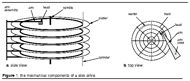
Each platter surface has an associated disk head responsible for recording (writing) and later sensing (reading) the magnetic flux variations on the platter's surface. The disk drive has a single read-write data channel that can be switched between the heads. This channel is responsible for encoding and decoding the data stream into or from a series of magnetic phase changes stored on the disk.
Significant fractions of the encoded data stream are dedicated to error correction. The application of digital signal processing may soon increase channel speeds above their current 100 megabits per second. (Multichannel disks can support more than one read/write operation at a time, making higher data transfer rates possible. However, these disks are relatively costly because of technical difficulties such as controlling the cross talk between the concurrently active channels and keeping multiple heads aligned on their platters simultaneously. The latter is becoming more difficult as track densities increase.)
The positioning components
Each data surface is set up to store data in a series of concentric circles, or tracks. A single stack of tracks at a common distance from the spindle is called a cylinder. Today's typical 3.5-inch disk has about 2,000 cylinders. As track densities increase, the notion of vertical alignment that is associated with cylinders becomes less and less relevant because track alignment tolerances are simply too fine. Essentially, then, we must consider the tracks on each platter independently.To access the data stored in a track, the disk head must be moved over it. This is done by attaching each head to a disk arm - a lever that is pivoted near one end on a rotation bearing. All the disk arms are attached to the same rotation pivot, so that moving one head causes the others to move as well. The rotation pivot is more immune to linear shocks than the older scheme of mounting the head on a linear slider.
The positioning system's task is to ensure that the appropriate head gets to the desired track as quickly as possible and remains there even in the face of external vibration, shocks, and disk flaws (for example, nonconcentric and noncircular tracks).
Seeking
The speed of head movement, or seeking, is limited by the power available for the pivot motor (halving the seek time requires quadrupling the power) and by the arm's stiffness. Accelerations of 30-40g are required to achieve good seek times, and too flexible an arm can twist and bring the head into contact with the platter surface. Smaller diameter disks have correspondingly reduced distances for the head to move. These disks have smaller, lighter arms that are easier to stiffen against flexing - all contributing to shorter seek times.A seek is composed of
- a speedup, where the arm is accelerated until it reaches
half of the seek distance or a fixed maximum velocity,
- a coast for long seeks, where the arm moves at its maximum
velocity,
- a slowdown, where the arm is brought to rest close to the
desired track, and
- a settle, where the disk controller adjusts the head to
access the desired location.
"Average" seek times are commonly used as a figure of merit for disk drives, but they can be misleading. Such averages are calculated in various ways, a situation further complicated by the fact that independent seeks are rare in practice. Shorter seeks are much more common[1,2], although their overall frequency is very much a function of the workload and the operating system driving the disk.
If disk requests are completely independent of one another, the average seek distance will be one third of the full stroke. Thus, some sources quote the one-third-stroke seek time as the "average". Others simply quote the full-stroke time divided by three. Another way is to sum the times needed to perform one seek of each size and divide this sum by the number of different seek sizes. Perhaps the best of the commonly used techniques is to weight the seek time by the number of possible seeks of each size: Thus, there are N - 1 different single-track seeks that can be done on a disk with N cylinders, but only one full-stroke seek. This emphasizes the shorter seeks, providing a somewhat better approximation to measured seek-distance profiles. What matters to people building models, however, is the seek-time-versus-distance profile. We encourage manufacturers to include these in their disk specifications, since the only alternative is to determine them experimentally.
The information required to determine how much power to apply to the pivot motor and for how long on a particular seek is encoded in tabular form in the disk controller. Rather than every possible value, a subset of the total is stored, and interpolation is used for intermediate seek distances. The resulting fine-grained seek-time profile can look rather like a sawtooth
Thermal expansion, arm pivot-bearing stickiness, and other factors occasionally make it necessary to recalibrate these tables. This can take 500-800 milliseconds. Recalibrations are triggered by temperature changes and by timers, so they occur most frequently just after the disk drive is powered up. In steady-state conditions, recalibration occurs only once every 1530 minutes. Obviously, this can cause difficulties with real-time or guaranteed-bandwidth systems (such as multimedia file servers), so disk drives are now appearing with modified controller firmware that either avoids these visible recalibrations completely or allows the host to schedule their execution.
Track following
Fine-tuning the head position at the end of a seek and keeping the head on the desired track is the function of the track-following system. This system uses positioning information recorded on the disk at manufacturing time to determine whether the disk head is correctly aligned. This information can be embedded in the target surface or recorded on a separate dedicated surface. The former maximizes capacity, so it is most frequently used in disks with a small number of platters. As track density increases, some form of embedded positioning data becomes essential for fine-grained control - perhaps combined with a dedicated surface for coarse positioning data. However, the embedded-data method alone is not good at coping with shock and vibration because feedback information is only available intermittently between data sectors.The track-following system is also used to perform a head switch. When the controller switches its data channel from one surface to the next in the same cylinder, the new head may need repositioning to accommodate small differences in the alignment of the tracks on the different surfaces. The time taken for such a switch (0.5-1.5 ms) is typically one third to one half of the time taken to do a settle at the end of a seek. Similarly, a track switch (or cylinder switch) occurs when the arm has to be moved from the last track of a cylinder to the first track of the next. This takes about the same time as the end-of-seek settling process. Since settling time increases as track density increases, and the tracks on different platters are becoming less well aligned, head-switching times are approaching those for track switching.
Nowadays, many disk drives use an aggressive, optimistic approach to head settling before a read operation. This means they will attempt a read as soon as the head is near the right track; after all, if the data are unreadable because the settle has not quite completed, nothing has been lost. (There is enough error correction and identification data in a misread sector to ensure that the data are not wrongly interpreted.) On the other hand, if the data are available, it might just save an entire revolution's delay. For obvious reasons, this approach is not taken for a settle that immediately precedes a write. The difference in the settle times for reads and writes can be as much as 0.75 ms.
Data layout
A SCSI disk appears to its client computer as a linear vector of addressable blocks, each typically 256-1,024 bytes in size. These blocks must be mapped to physical sectors on the disk, which are the fixed-size data-layout units on the platters. Separating the logical and physical views of the disk in this way means that the disk can hide bad sectors and do some low-level performance optimizations, but it complicates the task of higher level software that is trying to second-guess the controller (for example, the 4.2 BSD Unix fast file system).- Zoning. Tracks are longer at the outside of a platter than
at the inside. To maximize storage capacity, linear density should
remain near the maximum that the drive can support; thus, the amount
of data stored on each track should scale with its length. This is
accomplished on many disks by a technique called zoning, where adjacent
disk cylinders are grouped into zones. Zones near the outer edge have
more sectors per track than zones on the inside. There are typically
3 to 20 zones, and the number is likely to double by the end of the
decade. Since the data transfer rate is proportional to the rate at
which the media passes under the head, the outer zones have higher
data transfer rates. For example, on a Hewlett-Packard C2240 3.5-inch
disk drive, the burst transfer rate (with no intertrack head switches)
varies from 3.1 megabytes per second at the inner zone to 5.3 mbps
at the outermost zone.[3]
- Track skewing. Faster sequential access across track and
cylinder boundaries is obtained by skewing logical sector zero on
each track by just the amount of time required to cope with the most
likely worst-case head- or track-switch times. This means that data
can be read or written at nearly full media speed. Each zone has its
own track and cylinder skew factors.
- Sparing. It is prohibitively expensive to manufacture perfect
surfaces, so disks invariably have some flawed sectors that cannot
be used. Flaws are found through extensive testing during manufacturing,
and a list is built and recorded on the disk for the controller's
use.
So that flawed sectors are not used, references to them are remapped to other portions of the disk. This process, known as sparing, is done at the granularity of single sectors or whole tracks. The simplest technique is to remap a bad sector or track to an alternate location. Alternatively, slip sparing can be used, in which the logical block that would map to the bad sector and the ones after it are "slipped" by one sector or by a whole track. Many combinations of techniques are possible, so disk drive designers must make a complex trade-off involving performance, expected bad-sector rate, and space utilization. A concrete example is the HP C2240 disk drive, which uses both forms of track-level sparing: slip-track sparing at disk format time and single-track remapping for defects discovered during operation.
The disk controller
The disk controller mediates access to the mechanism, runs the track-following system, transfers data between the disk drive and its client, and, in many cases, manages an embedded cache. Controllers are built around specially designed microprocessors, which often have digital signal processing capability and special interfaces that let them controlhardware directly. The trend is toward more powerful controllers for handling increasingly sophisticated interfaces and for reducing costs by replacing previously dedicated electronic components with firmware.
Interpreting the SCSI requests and performing the appropriate computations takes time. Controller microprocessor speed is increasing just about fast enough to stay ahead of the additional functions the controller is being asked to perform, so controller over head is slowly declining. It is typically in the range 0.3-1.0 ms.
Bus interface
The most important aspects of a disk drive's host channel are its topology, its transfer rate, and its overhead. SCSI is currently defined as a bus, although alternative versions are being discussed, as are encapsulations of the higher levels of the SCSI protocol across other transmission media, such as Fibre Channel.Most disk drives use the SCSI bus operation's synchronous mode, which can run at the maximum bus speed. This was 5 mbps with early SCSI buses; differential drivers and the "fast SCSI" specification increased this to 10 mbps a couple of years ago. Disks are now appearing that can drive the bus at 20 mbps ("fast, wide"), and the standard is defined up to 40 mbps. The maximum bus transfer rate is negotiated between the host computer SCSI interface and the disk drive. It appears likely that some serial channel such as Fibre Channel will become a more popular transmission medium at the higher speeds, partly because it would have fewer wires and require a smaller connector. Because SCSI is a bus, more than one device can be attached to it. SCSI initially supported up to eight addresses, a figure recently doubled with the use of wide SCSI. As the number of devices on the bus increases, contention for the bus can occur, leading to delays in executing data transfers. This matters more if the disk drives are doing large transfers or if their controller overheads are high. In addition to the time attributed to the transfer rate, the SCSI bus interfaces at the host and disk also require time to establish connections and decipher commands. On SCSI, the cost of the low-level protocol for acquiring control of the bus is on the order of a few microseconds if the bus is idle. The SCSI protocol also allows a disk drive to disconnect from the bus and reconnect later once it has data to transfer. This cycle may take 200 ms but allows other devices to access the bus while the disconnected device processes data, resulting in a higher overall throughput.
In older channel architectures, there was no buffering in the disk drive itself. As a result, if the disk was ready to transfer data to a host whose interface was not ready, then the disk had to wait an entire revolution for the same data to come under the head again before it could retry the transfer. In SCSI, the disk drive is expected to have a speed-matching buffer to avoid this delay, masking the asynchrony between the bus and the mechanism.
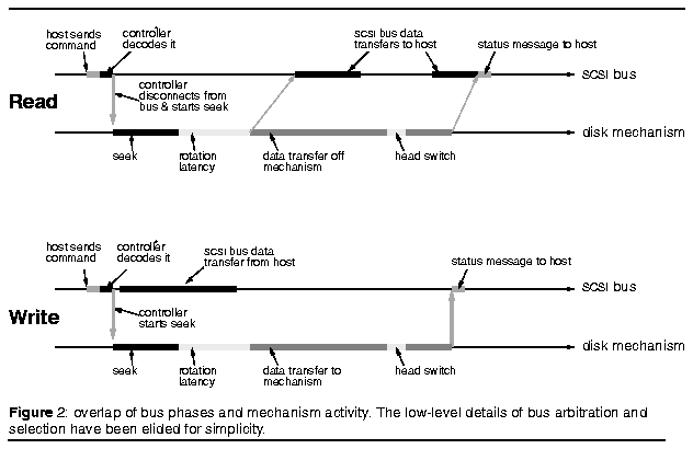
Since most SCSI drives take data off the media more slowly than they can send it over the bus, the drive partially fills its buffer before attempting to commence the bus data transfer. The amount of data read into the buffer before the transfer is initiated is called the fence; its size is a property of the disk controller, although it can be specified on modern SCSI disk drives by a control command. Write requests can cause the data transfer to the disk's buffer to overlap the head repositioning, up to the limit permitted by the buffer's size. These interactions are illustrated in Figure 2.
Caching of requests
The functions of the speed-matching buffer in the disk drive can be readily extended to include some form of caching for both reads and writes. Caches in disk drives tend to be relatively small (currently 64 kilobytes to 1 megabyte) because of space limitations and the relatively high cost of the dual-ported static RAM needed to keep up with both the disk mechanism and the bus interface.- Read-ahead. A read that hits in the cache can be satisfied
"immediately," that is, in just the time needed for the
controller to detect the hit and send the data back across the bus.
This is usually much quicker than seeking to the data and reading
it off the disk, so most modern SCSI disks provide some form of read
caching. The most common form is read-ahead - actively retrieving
and caching data that the disk expects the host to request momentarily.
- As we will show, read caching turns out to be very important when
it comes to modeling a disk drive, but it is one of the least well
specified areas of disk system behavior. For example, a read that
partially hits in the cache may be partially serviced by the cache
(with only the noncached portion being read from disk), or it may
simply bypass the cache altogether. Very large read requests may always
bypass the cache. Once a block has been read from the cache, some
controllers discard it; others keep it in case a subsequent read is
directed to the same block.
- Some early disk drives with caches did on-arrival read-ahead to
minimize rotation latency for whole-track transfers; as soon as the
head arrived at the relevant track, the drive started reading into
its cache. At the end of one revolution, the full track's worth of
data had been read, and this could then be sent to the host without
waiting for the data after the logical start point to be reread. (This
is sometimes - rather unfortunately - called a "zero-latency
read" and is also why disk cache memory is often called a track
buffer.) As tracks get longer but request sizes do not, on-arrival
caching brings less benefit; for example, with 8-Kbyte accesses to
a disk with 32-Kbyte tracks, the maximum benefit is only 25 percent
of a rotation time.
- On-arrival caching has been largely supplanted by simple read-ahead
in 0 which the disk continues to read where the last host request
left off. This proves to be optimal for sequential reads and allows
them to proceed at the full disk bandwidth. (Without readahead, two
back-to-back reads would be delayed by almost a full revolution because
the disk and host processing time for initiating the second read request
would be larger than the inter-sector gap.) Even here there is a policy
choice: Should the read-ahead be aggressive, crossing track and cylinder
boundaries, or should it stop when the end of the track is reached?
Aggressive read-ahead is optimal for sequential access, but it degrades
random accesses because head and track switches typically cannot be
aborted once initiated, so an unrelated request that arrives while
the switch is in progress can be delayed.
- A single read-ahead cache can provide effective support for only
a single sequential read stream. If two or more sequential read streams
are interleaved, the result is no benefit at all. This can be remedied
by segmenting the cache so that several unrelated data items can be
cached. For example, a 256-Kbyte cache might be split into eight separate
32-Kbyte cache segments by appropriate configuration commands to the
disk controller.
- Write caching. In most disk drives, the cache is volatile,
losing its contents if power to the drive is lost. To perform write
caching and prevent data loss, this kind of cache must be managed
carefully. One technique is immediate reporting, which the HP-UX file
system uses to allow back-to-back writes for user data. It allows
selected writes to the disk to be reported as complete as soon as
they are written into the disk's cache. Individual writes can be flagged
"must not be immediate-reported"; otherwise, a write is
immediately reported if it is the first write since a read or a sequential
extension of the last write. This technique optimizes a particularly
common case - large writes that the file system has split into consecutive
blocks. To protect itself from power failures, the file system disables
immediate reporting on writes to metadata describing the disk layout.
Combining immediate reporting with read-ahead means that sequential
data can be written and read from adjacent disk blocks at the disk's
full throughput.
- Volatile write-cache problems go away if the disk's cache memory
can be made nonvolatile. One technique is battery-backed RAM, since
a lithium cell can provide 10-year retention. Thus equipped, the disk
drive is free to accept all the write requests that will fit in its
buffer and acknowledge them all immediately. In addition to the reduced
latency for write requests, two throughput benefits also result: (1)
Data in a write buffer are often overwritten in place, reducing the
amount of data that must be written to the mechanism, and (2) the
large number of stored writes makes it possible for the controller
to schedule them in near-optimal fashion, so that each takes less
time to perform. These issues are discussed in more detail elsewhere.[2]
- As with read caching, there are several possible policies for handling
write requests that hit data previously written into the disk's cache.
Without nonvolatile memory, the safest solution is to delay such writes
until the first copy has been written to disk. Data in the write cache
must also be scanned for read hits; in this case, the buffered copy
must be treated as primary, since the disk may not yet have been written
to.
- Command queuing. With SCSI, support for multiple outstanding requests at a time is provided through a mechanism called command queuing. This allows the host to give the disk controller several requests and let the controller determine the best execution order - subject to additional constraints provided by the host, such as "do this one before any of the others you already have." Letting the disk drive perform the sequencing gives it the potential to do a better job by using its detailed knowledge of the disk's rotation position.[4,5]
3. Modeling disk drives
With this understanding of the various disk drive performance factors, we are ready to model the behavior of the drives we have just described. We describe our models in sufficient detail to quantify the relative importance of the different components. That way a conscious choice can be made as to how much detail a disk drive performance model needs for a particular application. By selectively enabling various features, we arrive at a model that accurately imitates the behavior of a real drive.
Related work
Disk drive models have been used ever since disk drives became available as storage devices. Because of their nonlinear, state-dependent behavior, disk drives cannot be modeled analytically with any accuracy, so most work in this area uses simulation. Nonetheless, the simplest models merely assume a fixed time for an I/O, or they select times from a uniform distribution. The more elaborate models acknowledge that a disk I/O has separate seek, rotation, and transfer times, but most fail to model these components carefully. Consider, for example, that- seek times are often modeled as a linear function of seek distance,
producing poor results for smaller seeks, which are the most common;
- uniform distributions are used for the rotational latency, although
they are inappropriate for nonindependent requests, which are frequent;
- media transfer times are ignored or modeled as a fixed constant
dependent on transfer size; and
- bus contention is often ignored when multiple devices are connected
to the same bus.
Some previously described work [2,6-8] used more detailed models that avoided many of the limitations described above. These models simulated axial and rotational head positions, allowing the seek, rotation, and transfer times to be computed instead of drawn from a distribution. This article is an extension of simulation work described earlier.[2]
The simulator
We built our event based simulator in C++ using a version of the AT&T tasking library[9] modified locally to support time as a double type rather than a long type. The tasking library provides a simple but effective simulation environment. In it, tasks represent independent units of activity; when they call delay(time), the simulated time advances. A task can also wait for certain low-level events; it is easy to construct a variety of synchronization mechanisms on top of these primitives. The basic ideas are readily applicable to other simulation environments. We model a disk drive as two tasks and some additional control structures (Figure 3). One task models the mechanism, including the head and platter (rotation) positions. This task accepts requests of the form "read this much from here" and "seek to there" and executes them one at a time. It also handles the data layout mapping between logical blocks and physical sectors. A second task, the direct memory access engine (DMA engine), models the SCSI bus interface and its transfer engine. This task accepts requests of the form "transfer this request between the host and the disk" and handles them one at a time. A cache object buffers requests between the two tasks and is used in a classic producer-consumer style to manage the asynchronous interactions between the bus interface and the disk mechanism tasks. 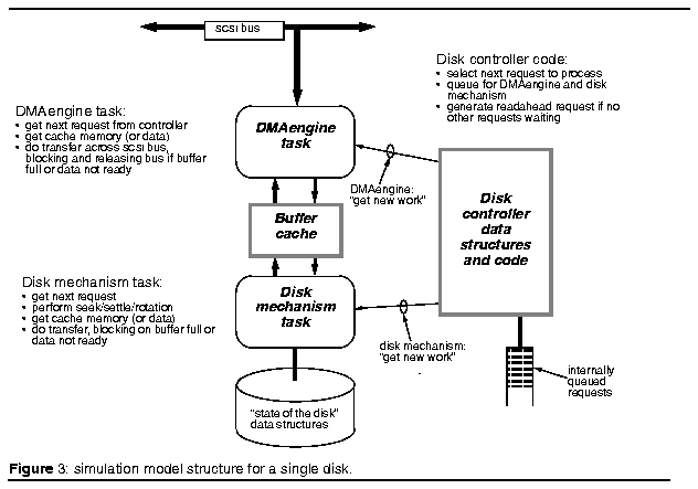
The disk drive model fits into a larger system that has items for representing the SCSI bus itself (a semaphore, so that only one device can use the bus at a time), the host interface, synthetic and trace-driven workload generator tasks, and a range of statistics-gathering and -reporting tools.
The disk-related portions of our simulation system consist of about 5,800 lines of commented C++ code. There are also around 7,000 lines of other infrastructure. The simulator can process about 2,000 I/Os per second on an HP9000 Series 800 Model H50 system, which has a 96-MHz PA-RISC 7100 processor. This allows about 1 million requests to be serviced in approximately 10 minutes.
Traces
For this study, we selected representative week-long samples from a longer trace series of HP-UX (Unix) computer systems. The systems and the traces have been described in much greater detail elsewhere.[2]For each request, the traces included data such as start and finish times with a granularity of 1 microsecond, disk address and transfer length, flags such as read/write, and whether the request was marked synchronous or not by the file system. The start time corresponds to the moment when the disk driver gives the request to the disk, and the finish time corresponds to when the "request completed" interrupt fires. The results we present here do not include time spent queued in the disk driver.
Table 1. Characteristics of the disk drives analyzed in this article.
------------------------------------------------------------------------------------
           Formatted                    Rotational   Average     Host interconnect
Disk type  capacity   Cylinders  Size   speed        8KB access  type      max speed
------------------------------------------------------------------------------------
HP C2200A  335 mb     1449       5.25"  4002 rpm     33.6 ms     HP-IB     1.2mb/s
HP 97560   1.3 gb     1935       5.25"  4002 rpm     22.8 ms     SCSI-2    10mb/s
------------------------------------------------------------------------------------
Table 1 describes the disks we singled out for analysis. Since our purpose is to show how the different components of a disk drive 7 model contribute to its accuracy, we selected a noncaching disk drive (the HP C2200A) as our first example so that the cache would not interfere with our analysis of the disk mechanism itself. Later we use the HP 97560 disk driven to show the effects of adding caching. The HP C2200A has an HP-IB (ieee488) bus instead of a SCSI interface. From a modeling perspective, the only major difference is that the HP-IB bus is slower than the disk drive mechanism; SCSI buses are usually faster. This tends to emphasize the importance of bus-related effects, as we will see.
Evaluation
For comparison, we need a metric to evaluate the models. A simple mean execution time for a request is of some value in calibrating a model to the real world, though it provides little differentiation between models. Instead, we plot the time distribution curves for the real drive and the model output and use the root mean square of the horizontal distance between these two curves as our metric. We call this the demerit figure of the model and present it in both absolute terms (as a difference in milliseconds) and relative terms (as a percentage of the mean I/O time). The real trace has a demerit figure of zero - that is, it matches itself exactly.We encourage other researchers using disk drive models to publish their demerit figures (and preferably the calibration curves). It is important to use a test workload similar to the kind of data one wishes to analyze. For example, a synthetic random I/O load is of little use in calibrating a model that is being used for workloads with a great many sequential data accesses.
We obtained the parameters for our models from the manufacturer's specifications, by performing curve fitting against the traces, and by direct measurement on the disk drives themselves.
No modeling
The simplest possible "model" uses a constant, fixed time for each I/O. Figure 4a plots two typical values from the literature (20 ms and 30 ms), together with the actual mean I/O time for the week's traced data. This model is not good. Even using the mean I/O time rather than a fixed estimate results in a demerit factor that is 35 percent of the average I/O time. 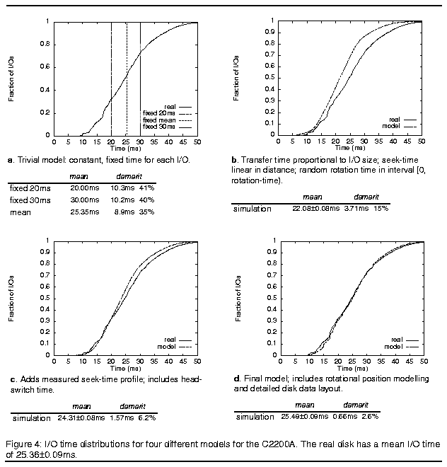
A simple model
To do better requires remembering state information between requests and modeling the effect of an I/O's length. A straightforward model that does this has the following combination of features:- a seek time that is linear with the distance, using the single-cylinder
and full-stroke seek times published in the disk drive specification
(see Figure 5),
- no head-settle effects or head-switching costs,
- a rotational delay drawn from a uniform distribution over the interval
[0, rotation time),
- a fixed controller overhead, and
- a transfer time linear with the length of the request. (There is
an asymmetry in transfer rates across the HP-IB bus: Reads run at
1 mbps, writes at 1.2 mbps. On the C2200A, the media transfer rate
of 1.9 mbps is faster than the HP-IB bus, so bus speed dominates.)
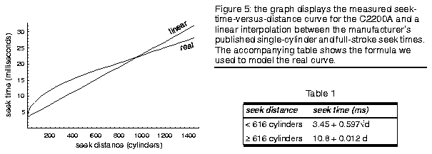
Figure 4b shows how this new model fares. We are now at a demerit of only 15 percent of a mean I/O time. This is better, but the demerit itself is still two to three times larger than many of the effects that I/O system designers wish to investigate.
Modeling head-positioning effects
The previous model used a seek time that was a linear function of distance. However, this is not a particularly good match, as Figure 5 shows. The mean difference between the linear seek model and the real one is 2.66 ms, which is a 9 percent error by itself. The table in Figure 5 describes the model we used to approximate the measured seek-time profile for this disk drive. Computing the better model is trivial - a six-line rather than a single-line calculation.Since we were improving our positioning calculations, we also took the opportunity to model the costs of head and track switching. This was achieved by determining which track and cylinder the request started on and where it ended, and then adding a fixed cost of 2.5 ms for each head and track switch needed to get from the start of the request to its end. Figure 4c shows that the demerit figure has more than halved to 6.2 percent of a mean I/O time.
Modeling rotation position
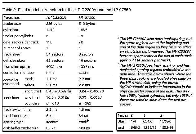
Only two important performance components are left to model on the C2200A: detailed rotational latency and spare-sector placement. By keeping track of the rotational position of the disk, we can explicitly calculate the rotational latency rather than just drawing it from a uniform distribution. This is done by calculating how many times the disk would have revolved since the start of the simulation, assuming it was spinning at exactly its nominally rated speed. The C2200A uses track and cylinder skewing and sector-based sparing with one spare sector per track. This needs to be accounted for in mapping logical blocks to the physical sectors.Adding all these factors results in the data shown in Figure 4d. This is a good match, with the model fitting the real disk drive to within 2.6 percent. Table 2 lists all the parameters used in this final model.
Modeling data caching
In the discussion so far we have used the C2200A disk drive because it has no buffer cache. When a cache is added to a disk drive, however, complications can arise. This is shown in Figure 6a, where a model incorporating all the features described so far is used to simulate an HP 97560 SCSI disk drive that uses both read-ahead and immediate reporting. The large disparity at small completion times is due to the caching, since about 50 percent of the requests are completed in 3 ms or less. Clearly, caching needs to be modeled if we are to get results closely matching the real disk drive. A demerit of 112 percent is not acceptable! 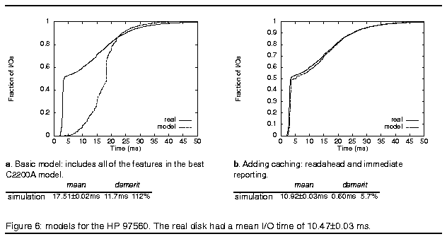
We added aggressive read-ahead and immediate reporting to the model, as described in the section "Caching of requests." This gave the results shown in Figure 6b. We consider this quite a good match, since the demerit is now only 5.7 percent of the mean I/O time; and since this mean is only half that of the C2200A, the absolute value of the error is comparable.
Two major remaining components can be modeled more accurately: (1) the actual bus speeds achieved in a particular system (these may be less than the drive's rated speed if the host I/O controller imposes a lower rate), and (2) the detailed disk drive controller overheads, which are frequently a combination of interactions between the previous request and the current one; these overheads also depend on the size of the request. Modeling at this level of detail requires heroic efforts, such as applying logic analyzers to SCSI buses. Bruce Worthington and Greg Ganger at the University of Michigan took this approach and managed to fine-tune the controller-overhead and bus-transfer components of a model similar to ours. They achieved demerit figures of 0.4 to 1.9 percent for an HP C2247 disk drive.[12]
Model summary
Table 3 summarizes the different models and how well they did; at the bottom we include a line for the University of Michigan model also. Clearly, the full model is necessary if a good match is required. Since it is not particularly onerous to implement, we encourage others to adopt it. Our full model includes the following details (parameters are provided in Table 2):- The host I/O device driver: the CPU costs for executing it, and
its queuing strategy.
- The SCSI bus, including bus contention effects.
- Disk controller effects: fixed controller overhead, SCSI bus disconnects
during mechanism delays, and overlapped bus transfers and mechanism
activity.
- Disk buffer cache, including read ahead, write-behind (immediate
reporting), and producer-consumer interlocks between the mechanism
and bus transfers.
- Data layout model: reserved sparing areas, including both sector-
and track-based models, zoning, and track and cylinder skew.
- Head movement effects: a seek time curve derived from measurements
on the real disks; settle time, with different values for read and
write; head-switch time; and rotation latency.
Table 3. Performance figures for the models of three disk drives
show greater accuracy as features are added to the model.

------------------------------------------------
feature                 demerit        disk type
------------------------------------------------
constant mean time      8.9ms    35%   HP C2200A
basic model             3.7ms    15%
add head positioning    1.3ms    6%
add rotation position   0.5ms    3%
no caching              11.7ms   112%  HP 97560
add caching             0.6ms    6%
controller costs        ~0.2ms   1%    HP C2247
-----------------------------------------------
An accurate model of a disk drive is essential for obtaining good simulation results from I/O studies. Failure to model disk drive behavior can result in quantitative - and in extreme cases, qualitative - errors in an analysis. Careful modeling is neither too difficult nor too costly. We have provided data that enables designers to quantitatively determine the benefits to be gained from investing effort in a disk drive model.
By far the most important feature to model is the data-caching characteristics of the disk (112 percent relative demerit if this is ignored). The next most important features to get right are the data transfer model, including overlaps between mechanism activity and the bus transfers (20 percent demerit), and the seek-time and head-switching costs (9 percent demerit). Although in our evaluation of the C2200A the transfer model had a greater effect than the positioning model, the relative importance will probably be reversed for SCSI drives because there the bus is generally faster than the disk mechanism.
Finally, modeling the rotational position and detailed data layout improved model accuracy by a further factor of nearly two. Modeling rotational position accurately is important for systems that emphasize sequential transfers, which modern file systems are becoming increasingly adept at doing.
Even a good model needs careful calibration and tuning. For example, some of the values we used to get a good fit in our models differ from the manufacturer's published specifications. In addition, we did not have space here to present the quantitative effects of modeling zoning (although our model handles it). These features and others may become particularly important when a workload has large data transfers.
We plan to use our refined disk drive simulation model to explore a variety of different I/O designs and policy choices at host and disk drive levels. We hope to make the source code of our model available to interested researchers later this year, together with calibrated model parameters for a longer list of disk drive types than we have space to describe here.
4. Acknowledgments
Pei Cao contributed greatly to the simulator of which our disk model is a part, and Marvin Keshner provided information on several of the underlying storage technology trends. Tim Sullivan and Patricia Jacobson provided helpful feedback on earlier drafts of this article. This work was performed as part of the DataMesh research project at Hewlett-Packard Laboratories.
5. References
1. D.A. Patterson and J.L. Hennessy, Computer architecture: a quantitative approach, Morgan Kaufmann, San Mateo, Calif., 1990.2. C. Ruemmler and J. Wilkes, "Unix disk access patterns," Proc. Winter 1993 Usenix Conf., Usenix, Sunset Beach, Cali£, Jan. 1993, pp. 405-420.
3. Hewlett-Packard Co., Boise, Idaho, HP C2240 series 3.5-lnch SCSI-2 disk drive: technical reference manual, part number 5960-8346, 2nd ed., Apr. 1992.
4. M. Seltzer, P. Chen, and J. Ousterhout, "Disk scheduling revisited," Proc. Winter 1990 Usenix Conf., Usenix, Sunset Beach, Calif., Jan. 1990, pp. 313-323.
5. D.M. Jacobson and J. Wilkes, "Disk scheduling algorithms based on rotational position," Tech. Report HPL-CSP-91-7, Hewlett-Packard Laboratories, Palo Alto, Calif., Feb. 1991.
6. C.A. Thekkath, J. Wilkes, and E.D. Lazowska, "Techniques for
file system simulation," published simultaneously as Tech. Reports
HPL-92-131 (Hewlett-Packard Laboratories, Palo Alto, Calif.) and 92-0908
(Dept. of Computer Science and Eng., Univ. of Washington, Seattle, Wash.).,
Oct. 1992.
[It has since been published in: Software - Practice and Experience
24(11):981--999 (Nov. 1994).]
7. C. Ruemmler and J. Wilkes, "Disk shuffling," Tech. Report HPL-91-156, Hewlett-Packard Laboratories, Palo Alto, Calif., Oct. 1991.
8. M. Holland and G.A. Gibson, "Parity declustering for continuous operation in redundant disk arrays," Proc. Fifth Int'l Conf. Architectural Support for Programming Languages and Operating Systems, published as a special issue of Computer Architecture News, Vol. 20, 1992, pp. 23-35.
9. Unix System V AT&T C++ Language System release 2.0, selected readings, AT&T select code 307-144, 1989.
10. Hewlett-Packard Co., Boise, Idaho, HP series 6000 disk storage systems owner's manual for models 335H, 670H, and 670XP, part number C220090901, Feb. 1990.
11. Hewlett-Packard Co., Boise, Idaho, HP 97556, 97558, and 97560 5.25-lnch SCSI disk drives: technical reference manual, part number 5960-0115, June 1991.
12. B. Worthington, G. Ganger, and Y. Patt, "Scheduling algorithms for modern disk drives," Proc.ACM SlGMetrics Conf., May 1994, pp. 241-251.
 Chris Ruemmler
is a software engineer at Hewlett-Packard, where he works in the area of performance analysis. His technical interests include architectural design, system performance, and operating systems. He graduated with BA and MS degrees in computer science (1991 and 1993, respectively) from the University of California at Berkeley.
 John Wilkes
has worked since 1982 as a researcher and project manager at Hewlett-Packard
Laboratories. His current research interest is high-performance, high-availability
storage systems. He is also interested in performance modeling, and interconnects
and resource management for scalable systems. He enjoys interacting with
the academic research community. Wilkes graduated from the University
of Cambridge with BA and MA degrees in physics (1978 and 1980, respectively)
and a Diploma and PhD in computer science (1979 and 1984, respectively).
Wilkes can be contacted at Hewlett-Packard Laboratories, MS lU13, 1501 Page Mill Rd., Palo Alto, CA 94304-1126. Ruemmler's address is Hewlett-Packard Co., 19111 Pruneridge Ave. MS 44UG, Cupertino, CA 95014.